
Built for All Civil Designers
With Civil Site Design you can quickly and easily generate road network designs complete with dynamic intersections and cul-de-sacs, updating as you make changes to any element. The software is also purpose built for road reconstruction designers. Generate outputs including long and cross section sheets, setout points, volume reports and more, directly into your drawing environment and customisable to suit your local drafting standards.
In Civil 3D, Civil Site Design uses the surfaces and alignments in Civil 3D, and can export surfaces, alignments, profiles and corridors and COGO points directly to the drawing.
For CAD based systems, Civil Site Design comes complete with surface modelling and alignment design tools, as well as dynamic site grading functionality.
Civil Site Design focuses on the following design areas:
Road Design
About
Road Subdivision
Road Reconstruction
Highway Design
Rural Road
Driveway Clearance
Pipe Design
Pipe Design
Stormwater Design
Sewer Design
Site Grading
Site Grading
Surface Modeling
Surface Modeling
Alignment Design
Alignment Design
HEC-RAS Exchange
HEC-RAS Exchange
Comprehensive Tools – Complete Control
Civil Site Design (CSD) has been developed to provide road design and outputs directly inside AutoCAD, Civil 3D and BricsCAD.
Our philosophy of combining template and string based design, as well as automating common design elements such as intersections and roundabouts, provides a familiar and complete set of tools for rapid creation and output of your road subdivision, reconstruction, rural, highway and other design projects.
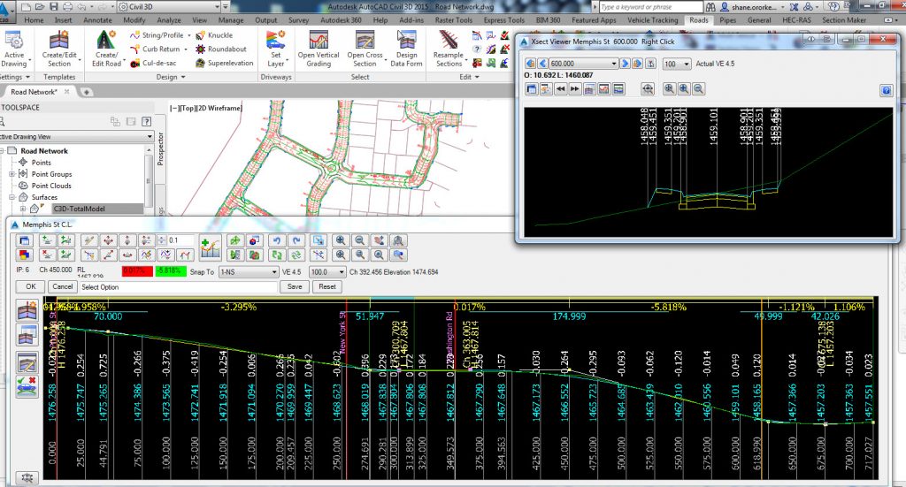
With the Vertical Design Windows you get complete access to any selected design element including editing the vertical design profiles and cross sections, establish cut/fill bulking factors, generating summary volume reports and creating surface models of your designs. You can position your vertical (long section) design windows as well as cross section windows anywhere on your monitor/s and see everything update as you make changes.
Since you can have multiple profile strings open simultaneously you can see your roads, kerb returns, cul-de-sacs and knuckle strings update as you edit your main roads. With multiple cross section windows open, you can track the impacts of your profile edits as you graphically make changes. And you can check the impacts over a range of chainages, rather than one at a time.
The Road design tools can be used for any generic corridor design: open channels, retaining walls, footpaths, etc.
Plotting and Publishing to Your Local Drafting Standards
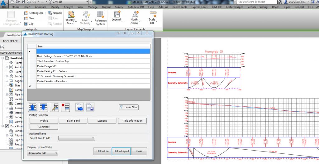
CSD has all the tools you need to rapidly generate industry standard outputs of your designs directly inside the drawing, ready for immediate plotting. For Australian (and many European) customers the default plotting output styles that install with the software will likely suit your requirements.
With CSD you can interactively control the sheet layout, scales, layers and linetypes as well as what to present in your outputs. Plotting outputs styles can be saved for reuse – output them to separate drawings or as layouts in the current drawing.
Setout, plan plotting of the models and slope patterns are all created directly inside your drawing.
You can decide whether to output to layout tabs or to external drawings.
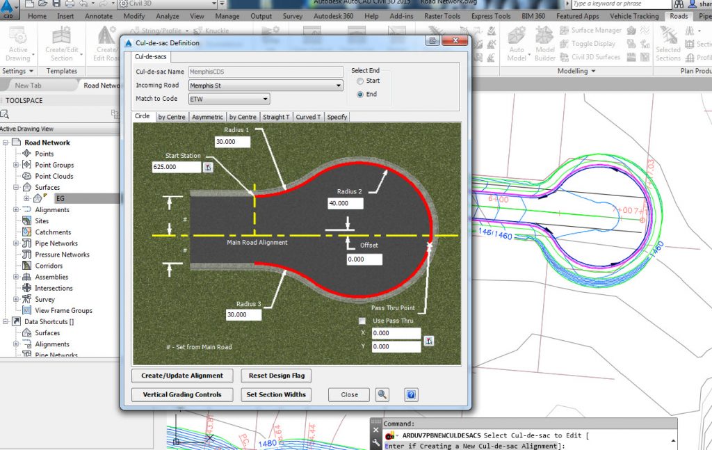
With CSD you can completely automate your road subdivision design processes using intelligent objects to handle common design elements such as intersections, kerb returns, cul-de-sacs, roundabouts and knuckles.
Kerb returns automatically and dynamically position themselves both horizontally and vertically to the intersecting roads. Design wizards allow for user creation of single or multi radius kerb returns, or use of your own alignments. The auto kerb return function creates multiple kerb returns at once, all matched to the intersecting roads and with cross sections automatically matching between the main and side roads.
Cul-de-sac design can be parametrically driven with support for circular, asymmetric, tear-drop, Y and T shaped configurations. After setting the values CSD will lay it out horizontally and vertically to match the incoming Road and with cross sections automatically matching the road at either end.
The Roundabout tools allow the designer to quickly establish elevations around your selected island and edge of carriageway alignments to suit your intersection levels, as well as assigning cross sections to describe your internal island.
Localised road widening is easily achieved using the Knuckle tool, which creates a localised widening that stay attached to the Road as you make design changes.
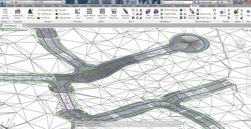
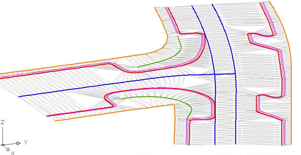
At the click of a button a surface model is created incorporating all the road, kerb returns, cul-de-sacs, roundabouts and knuckles including all trimming of strings at intersections and automatic inclusion of boundaries to trim the extents and hide internal areas.
Road Reconstruction
CSD has been developed with road reconstruction in mind. Featuring advanced cross section subgrade tools, independent vertical and/or horizontal control over any part of your cross section, and the ability to form models using any collection of independently graded strings and cross section codes, CSD is the premium design tool for road reconstruction works.
Specific vertical design tools are included to help automate road reconstruction processes, including the ability to automatically design based on resheet/overlay depths, match surface controls and string/code projections, as well as displaying design ‘envelopes’ (projections from another string/code at grade).
Advanced cross section design tools allow you to manage your cross sections easily and the dynamic cross section viewer allows you to review your edits as you make them.
Using the subgrade design tools you can generate accurate volume outputs through multiple layers, with automatic adjustment of pavement layer depths to match existing surfaces.
CSD’s advanced modelling tools allow you to put together any collection of roads, strings and cross section codes, over user-selected chainage ranges, to allow for all your design requirements.
Major Road and Highway Design
Major Road and Highway Design invariably involves larger scale designs that may include service roads, multiple divided carriageways, grade separated intersections, and multiple design teams working on different sections.
Civil Site Design delivers with:
- Complete user control over cross sections
- Design-controlled batter (daylighting) outputs for accommodating elements such as ditches, benching and multiple batter slope conditions
- Scalability – design in one project what you would normally split up into 5 smaller projects and still achieve high speed performance during design
The CSD design environment is a proven performer on large scale projects, with our customers reporting excellent performance when designing single projects in excess of 19km and managing surface data containing over a million points. With AutoCAD Civil 3D you can work with multi-million point surfaces.
CSD includes specific design tools for highway designers in managing grade separated roads, as well as intelligent design tools for managing multiple benching conditions and ditches.
Rural Road Design
The rural road design tools build upon the extensive road design tools for automating the profile design based on minimum pavement depths and the ability to edit cross section elements using alignment, string and surface constraints. Typical of rural road design type projects, you can apply pavement superelevation and include rules-based ditches.
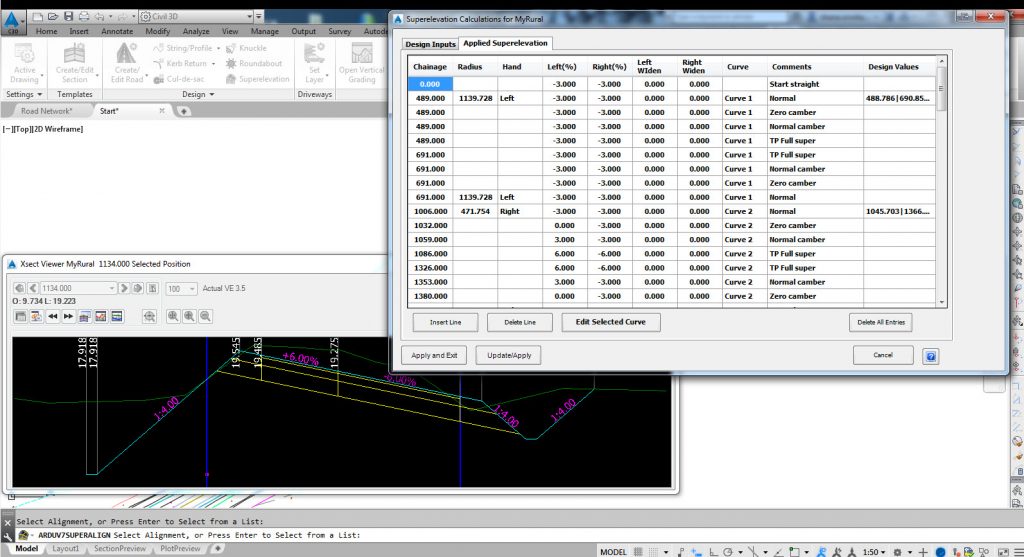
After setting a speed for the road length, you can select to apply Australian (or user defined for your region) superelvation rules to establish changes to pavement crossfall through each curve – Civil Site Design will calculate and apply the required superelevation through each curve based on the speed, curve radius and maximum superelevation.
The superelevation ‘table’ is a simple text file, so you can easily edit it to meet your regional requirements.
Shoulder codes can similarly be adjusted through curves, by applying a relative shoulder rotation – again you have control over how the shoulder rotates, relative to the pavement rotations. You can override the applied superelevation at each curve, either by directly editing chainages and crossfalls, or by re-applying a superelevation length and the maximum super to apply.
After applying superelevation you still have ultimate override control using the cross section Variation tools.
Civil Site Design includes an automated tool to add simple ditches that check for fill conditions on the ditch bottom and remove the ditch when not required. You can also apply independent vertical (profile) control and horizontal (alignment) control to ditches, and set for ditches to automatically be removed in certain fill or certain cut situations. With the conditional batter tools you can establish a rules based approach to the ditch and embankment designs to automatically include/remove ditches, add benching, change batter slopes and more, all based on depth range conditions you set.
Integrated Driveway Design Tools
As well as providing comprehensive civil design tools for road and site grading projects, Civil Site Design integrates driveway tools into your design workflow to instantly identify and design to avoid vehicle clearance conflicts.
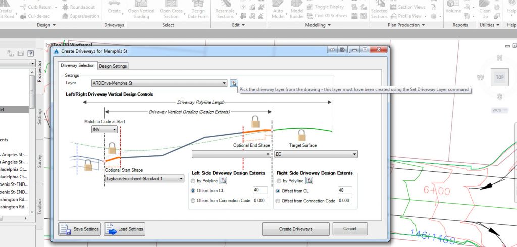
The driveway tools work from polylines in the drawing and link dynamically to both Road design cross sections and the property boundary. You can see your vehicle clearance requirements update as you edit your Road and vertically design your driveway to avoid vehicle clashes.
It’s simple to use and gives you instant feedback. Included is a compliance check tool to highlight driveways where vehicle clash/es occurs.
Open each driveway in the Driveway Vertical Grading Editor window and choose what vehicle clearance template to apply. See the vehicle clearance line and all vertical clashes highlighted.
You can design the driveway by adding, deleting and editing IP’s to remove clearance problems—updates will occur dynamically as you change the vertical design.
You can create your own vehicle clearance templates to suit your local conditions, and check each for compliance.
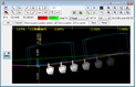
Civil Site Design Pipes includes all the tools you need to quickly create your pipe networks and avoid crossing services and other pipe networks.
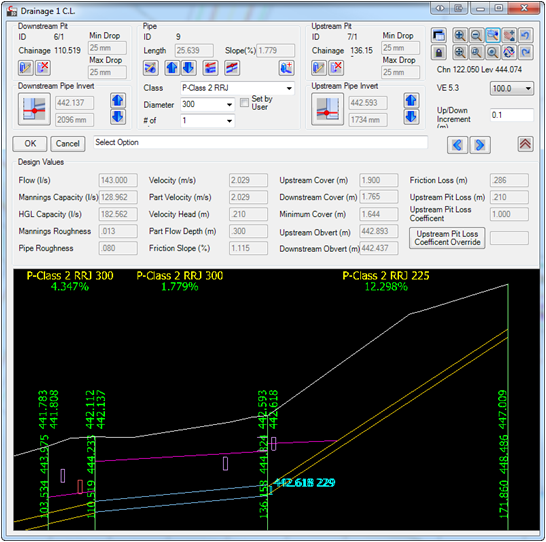
Working inside the drawing environment, you can create and design Stormwater Drainage Networks, Sewer Networks and undertake general pipe design. Service obstruction checks are included in the design process for you to quickly optimise your designs and avoid conflicts between underground services.
Layout and create your pipe network by either clicking on screen or create directly from polylines or alignments. Whilst the initial pipe layout is based on minimum slopes and covers, the multiple Vertical Design Windows allow you to quickly adjust any pipe sizes and levels to achieve your desired outcomes.
From The Vertical Design Window interface you can see all crossing pipes and services, including clash detection. Edit pipes and pits by setting invert/obvert levels or move pipes up and down by increment. Insert in-line pipes wherever you require and review the pit drops and pipe levels.
Civil Site Design Pipes is synchronised with the Roads module, enabling both the pit levels and offsets to be directly connected to a road element and with dynamic updates as the road element is edited. All pipe networks can be displayed on the road Vertical Grading and Cross Section Windows to confirm locations relative to the road design.
The Reports Manager builds customised reports from any combination of attributes stored by the software and can be exported as comma separated files (CSV) for review in your preferred spread-sheet program or as an AutoCAD table in the drawing. Create pit and pipe schedules directly from your designs.
Using the Long Section plotting tools you can rapidly generate an industry standard output for your designs directly inside the AutoCAD drawing with control over the sheet layout and data included. Publish directly to AutoCAD as separate files or as layouts in the current drawing.
Built specifically for the Australian stormwater drainage designer and applying the principles of the Australian Rainfall and Runoff manual and Rational Method design, Civil Site Design Pipes is a complete tool for designers wanting to create underground stormwater drainage systems.
Easily create drainage catchments directly from a Surface and polyline – catchment style libraries allow you to easily assign catchment criteria for common catchment types.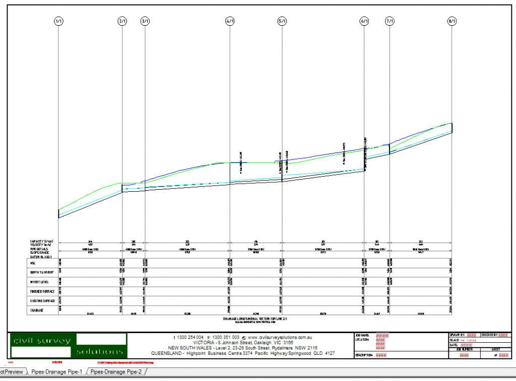
When a network is created the design flows are calculated and pipe sizes and levels are automatically assigned to manage the flows as well as minimum cover, slope and flow velocities.
As you make changes to pipe sizes and levels the Hydraulic Grade Line and all design information for each pipe automatically updates.
Using the Long Section plotting tools you can rapidly generate industry standard outputs of your designs directly inside the AutoCAD drawing, complete with HGL and other stormwater details and ready for immediate plotting. Publish directly to AutoCAD as separate files or as layouts in the current drawing.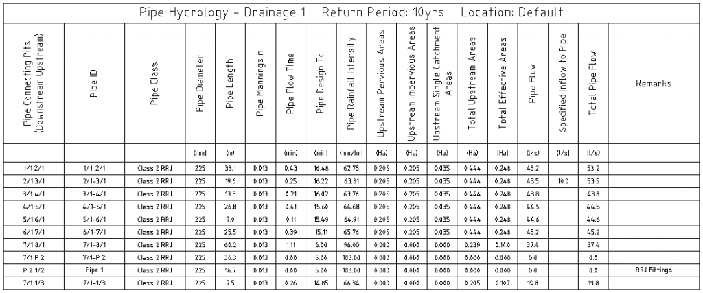
Civil Site Design Pipes incorporates a comprehensive set of sewer pipe design tools.
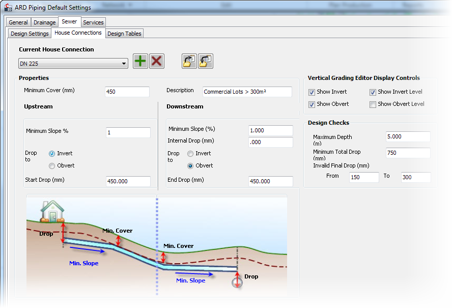
Sewer house/property connections are included in the design tools and can check depth controls and minimum levels along the sewer network. Each house connection can be viewed in a Vertical Design window for editing and adjustment.
The sewer network will automatically adjust to ensure compliance with the minimum house connection levels, and you will be alerted if sewer pipe edits result in any compliance issues with house/property connections.
Interactive vertical design windows are able to display any branch of pipes in a network and complete with editing tools you can quickly and easily design a system to avoid all conflicts and service the house/property connection. All house connections, service obstructions and other networks display as crossing pipes, including clearance controls – as you make changes to pipe sizes and levels you can immediately identify and address any conflicts.
Detailed and specific reporting tools for sewer designers enable quick identification of any house/property connection issues.
Using the Long Section plotting tools you can rapidly generate industry standard outputs of your designs directly inside the AutoCAD drawing, including house connection controls and ready for immediate plotting. Publish directly to AutoCAD as separate files or as layouts in the current drawing.
Plan drafting occurs directly in the AutoCAD drawing including selected attributes from your design specific to sewer design.
Civil Site Design for Site Grading
Built for rapid design of features such as building pads and detention basins, the dynamic grading tools automatically clean up internal overlapping corners and include radial and mitre options on external corners.
With the Site Grading tools you can take a polyline, apply a cross section template (assembly) to create a graded surface complete with corner cleanup. The surface and grading linework automatically updates as you edit your grading, so you get immediate feedback on the impact of your design changes, as you make them.
You can immediately review volume outputs after making design changes, enabling easy volume checking and optimization. Use the Civil Site Design Surface Modelling tools to create one total dynamic surface model incorporating all your land development components – perfect for lot grading.
If you’re using Civil 3D, this is a rapid creation alternative to the Civil 3D grading tools, supporting a total cross section extraction along a polyline and with corner cleanup. Volume calculations in Civil 3D can be made by exporting the grading surface out as a Civil 3D surface object.
The grading tools support cross section templates (assemblies) and intelligent batter designs to address specific site design requirements. As well, you can combine template and string based designs into the grading models to get the fine level of control you require.
The quick elevation viewer makes it even easier to apply changes to your grading string levels and see the results. You can use both the vertical grading design tools and the quick elevation viewer to make edits to the design – change IP positions along the grading, edit and add vertical curves, either in a grid view or using a graphical vertical design display.
Civil Site Design Surface Modeling
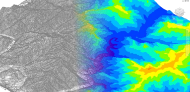
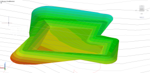
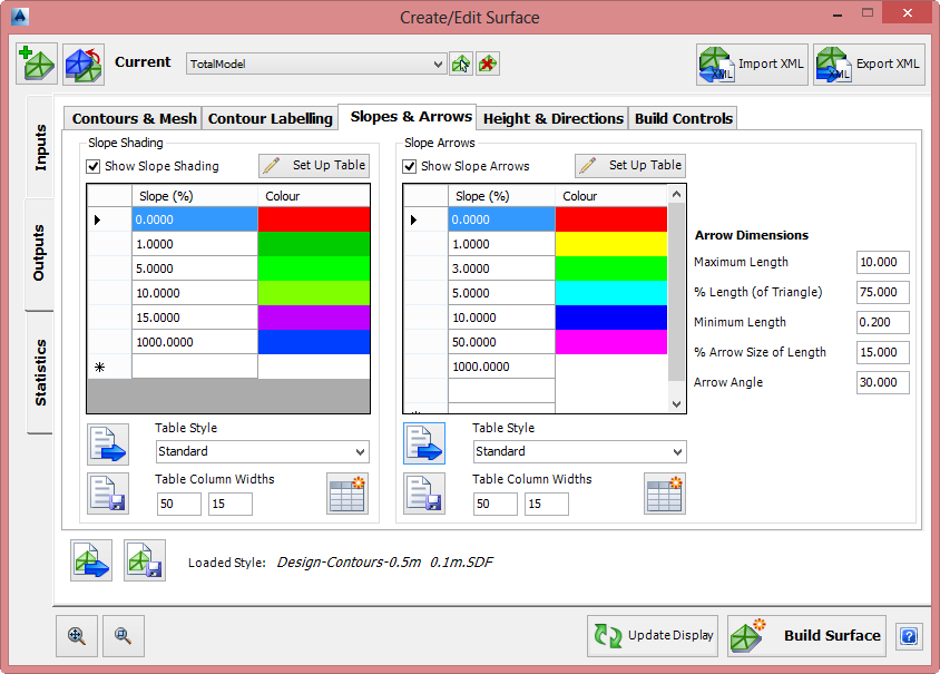
Surface creation is quick and easy with support for multiple data inputs, intuitive display controls and outputs dynamically represented directly inside the drawing, ready for plotting and publishing.
The Surface model inputs support external point data and Land XML files as well as reading 3D data directly from the drawing. Surface display controls are immediately accessible to you, allowing for fast and dynamic adjustments to contour intervals, colors, layers, contour labeling and surface analysis.
Analyse your surface to with tools to show elevation banding, slope ranges, directions and slope arrows coloured to your design requirements. Create tables of your surface analysis as AutoCAD tables, ready for plotting and publishing.
LandXML file transfer is fully supported so surface data can be imported and exported readily across multiple design platforms. Create and edit your surfaces in Civil Site Design with the confidence of being able to immediately share that information with the broader design community.
Surface objects can be selected by mouse click in the drawing and edited. Surface data can also be exported to AutoCAD entities as desired, for sharing with any AutoCAD user.
Obtain volume reports between any two surfaces, including accounting for compaction factors and applying height adjustments. Volume reports can be exported to a text file for re-use in the drawing and for other documentation purposes.
In AutoCAD Civil 3D, Civil Site Design can work directly with the Civil 3D surface objects.
Full Feature Surveys – Stringer Topo
For surveyors, the Stringer Topo software delivers a comprehensive topographical field-to-finish modeling solution. Stringer Topo converts raw survey data into COGO points in the drawing, stylized based on point codes, and adds breaklines to the surface automatically from the surveyed points.
Civil Site Design – Alignment Design
It’s simple and easy in Civil Site Design – draw a polyline and click to turn it into an alignment object. Labeling is fully automatic and user customisable as is the line, arc and spiral display.
Alignments can be easily edited during the creation process or via the alignment editing tools – users just click to edit an IP and get access to tools to change the spiral lengths, curve radius and IP position. Add IP’s, delete and move IP’s within the one editing environment.
When you make an edit to the alignment geometry the display updates in the drawing, including the labelling.
Label display is customizable by you, with a simple interface for the addition of blocks, arrows, lines, circles and text in the chainage labeling, on user defined AutoCAD layers. In AutoCAD, labels react with the drawing scale in model space so there is less work trying to get the size right for plotting, and labels flip to be plan readable in the model. Set your own standards for labeling including sampling intervals for major and minor chainages.
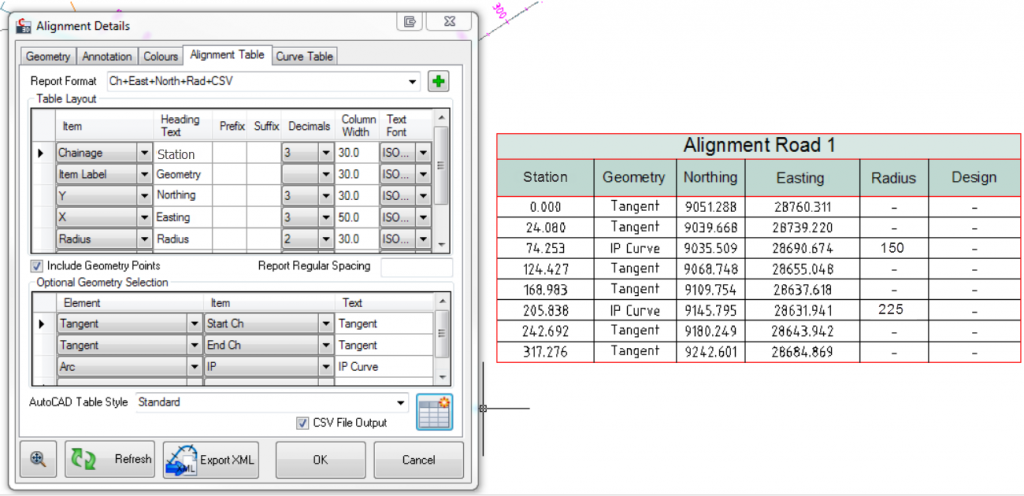
Create alignment tables when you create or edit your alignment. You select the information to include in Alignment Tables and Curve Tables and then generate AutoCAD tables at the click of a button. As part of the editing process the AutoCAD tables can be updated in the drawing after the geometry of the alignment changes.
As changes are made to the design, the drafting updates in your drawing, ready for plotting and publishing.
Data share is made easy via Land XML transfer. Import and export alignment geometry across multiple design platforms.
In AutoCAD Civil 3D, Civil Site Design works directly with the Civil 3D alignment objects.
Civil Site Design includes an optional HEC-RAS menu which provides users with the ability to transfer section data to HEC-RAS for river analysis, including assignment of Mannings coefficients, defining overbank areas, skewed sections, houses and ineffective areas.
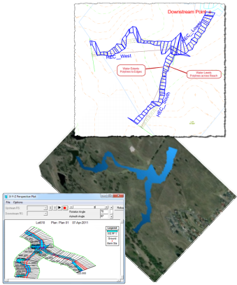
Waterline results from HEC-RAS can be exported back to Civil Site Design for presentation in the drawing and construction of a water surface.
Civil Site Design supports multiple platforms and multiple product releases:
Civil Site Design has been developed to operate on AutoCAD, Map 3D and Civil 3D from 2012 to the latest release, and recently has been updated to operate on BricsCAD.
Select your product(s) below. When your cart is complete, you will be directed to a secure site to enter credit card information. We do not retain any of your information
![]()